
When designing RF solution, RF filters play prominent roles in the system. If picking RF filter, the following parameters should be considered.
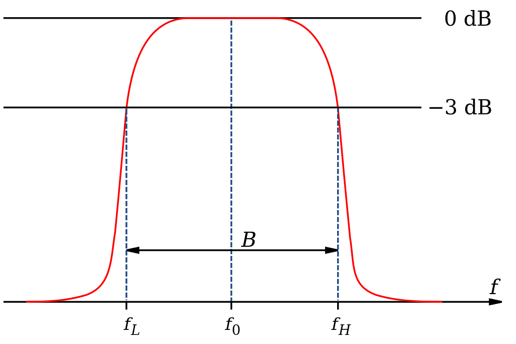
1. Center frequency: f0 is short for the center frequency of the passband of the RF filter, which is generally taken as f0 = (fL+ fH) /2, and fL and fH are the side frequency points of the relative 1dB or 3dB drop from the left and right of the band-pass or band-stop filter. The pass-band bandwidth of narrowband filters is usually calculated by taking the minimum insertion loss as the center frequency.
2. Cutoff Frequency: For the low-pass filter, it refers to the right frequency point of the passband, and for the high-pass filter, it refers to the left frequency point of the passband, which is usually defined in terms of 1dB or 3dB relative loss points. The reference for relative loss is as follows: for low pass filter, the insertion loss is based on DC, and for high pass filter, the insertion loss is based on the highest high-pass frequency without spurious stop-band.
3. BWxdB: Refers to the spectrum width to be crossed, BWxdB= (fH-FL). fH and fL are the corresponding left and right frequency points at X (dB) lowered based on insertion loss at center frequency f0. X=3, 1, 0.5, namely BW3dB, BW1dB, BW0.5dB, are usually used to characterize the pass-band bandwidth parameters of the filter. Fractional bandwidth =BW3dB/f0×100%, also commonly used to characterize the pass-band bandwidth of the filter.
- Insertion Loss: Due to the RF filter, the original signal in the circuit is attenuated, its loss is characterized at the center or cutoff frequency. If the requirement of full-band loss should be emphasized.
- Ripple: Refers to the peak-to-peak of insertion loss fluctuation with frequency based on the mean loss curve in the range of 1dB or 3dB bandwidth (cut-off frequency).
- Passband Riplpe: It refers to the change of insertion loss in the pass-band frequency. The pass-band fluctuation in 1dB bandwidth is 1dB.
- VSWR: It is an important indicator to measure whether the signal in the pass-band of a filter is well-matched and transmitted. VSWR= 1:1 is for ideal match, VSWR > 1 is for mismatch. For an actual RF filter, the bandwidth satisfying VSWR < 1.5:1 is generally less than BW3dB, and its proportion to BW3dB is related to the filter order and insertion loss.
- Return Loss: It refers to the ratio decibels (dB) of the input power and reflection power of the signal port, also which is equal to |20Log10ρ|, ρis voltage reflection coefficient. The return loss is infinite when the input power is absorbed by the port.
- Stopband rejection: an important index to measure the selection performance of RF filter. The higher the index is, the better the suppression of out-of-band interference signal is. There are usually two formulations: one is to ask how much dB fs is suppressed for a given out-of-band frequency, and the calculation method is the attenuation as-il at FS; The other is to propose an index to characterize the degree of proximity between the amplitude-frequency response of the filter and the ideal rectangle -- rectangle coefficient (KxdB > 1), KxdB=BWxdB/BW3dB, (X can be 40dB, 30dB, 20dB, etc.). The more orders the filter has, the more rectangular it is -- that is, the closer K is to the ideal value of 1, the more difficult it is to make.
Of course, except above factors, you may consider its working power, the measurement for the application, or for indoor or outdoor usage, as well as the connectors. However, the above parameters are most important to decide its performance.
As the designer of RF filters, Jingxin can help you out on the issue of RF filters, and customize the passive filter according to your solution. More detail can be consulted with us.
Post time: Oct-08-2021


